Pycom LoPy4
This tutorial is made to showcase the use of Pycom LoPy4 board to create a LoRaWAN enabled sensor node. In the following example, a temperature and humidity sensor was used with the Pycom LoPy4 board.
Hardware
Microcontroller
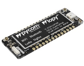
LoPy4 from Pycom. LoPy4 pinout, documentation, example code.
The Pycom LoPy4 is a microcontroller board offering many radio frequency (RF) connection options, namely LoRa (and LoRaWAN), SIGFOX, Bluetooth (Classic and Low Energy, BLE), and WiFi. In contrast to most other microcontroller boards the LoPy4 is programmed in MicroPython, which is a special subset of the Python 3 programming language and libraries for microcontrollers. The module is operated by the Espressif ESP32 microcontroller board, which contains a dual-core Xtensa 32bit LX6 processor running with up to 240MHz, 8 MB of flash memory (to store the program code and some files within a file system), and 520 KB of RAM (to store variables, status information, and buffers). The ESP32 module also has built-in WiFi and Bluetooth LE connectivity. In addition, the LoPy4 has 4 MB of PSRAM (pseudo static RAM) that is used as a memory extension for the ESP32. The operating voltage of the board is 3.3V (this is important when attaching sensors and other peripherals; they also must operate on 3.3V). The board offers 18 general purpose input/output pins (18 GPIOs), from which up to 12 can be used as analog input pins (with 12bit analog digital converters (ADC)) and two as analog output pins (8bit digital analog converter (DAC)). Most GPIO pins can be configured for specific hardware protocols. In total 3 serial ports (programmable Universal Asynchronous Receiver and Transmitter, UART), 2 I2C ports, 3 SPI ports, 1 CAN bus, 1 PWM channel, and an I2S port can be utilized. The board has a built-in RGB LED that can be programmed by the user. The LoPy4 is available from the manufacturer for around 35 €.
The LoPy4 needs to be operated on 3.5V – 5.5V put to the VIN pin. The onboard regulator brings it down to 3.3V. The 3.3V pin can only be used as an output. Do not feed 3.3V into this pin as this could damage the regulator. The board can be programmed over the serial interface, or via WiFi using a telnet or FTP connection. By default, the LoPy4 acts as a WiFi access point (SSID: lopy4–wlan–XXXX, Password: www.pycom.io) and a user can connect to the module after joining the WiFi network in order to upload user programs and data files.
A WiFi and Bluetooth antenna is mounted on the LoPy board, but also an external antenna can be connected via an SMA-type connector. The LoRa or SIGFOX antenna has to be connected via an SMA-type connector. The LoRa transmitter and receiver is encapsulated within a LoRa module. It uses the LoRa chip SX1276 from the company Semtech and can be configured to work either in the 433 MHz, 868 MHz, or 915 MHz frequency band. The LoRa module is connected via SPI interface to the microcontroller and all of the required connections of the LoRa transceiver pins with the microcontroller are already built-in on the LoPy4 board. Since the module only implements the LoRa physical layer, the LoRaWAN protocol stack is implemented in software on the microcontroller. The implemented LoRaWAN functionality is compatible with LoRaWAN Class A/C.
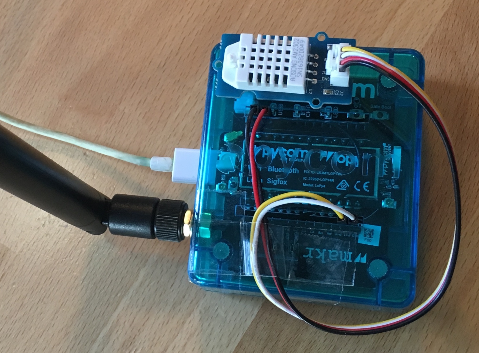
The Pycom LoPy4 with the Expansion Board 3 (inside the blue case) and an externally attached DHT22 temperature and humidity sensor.
Expansion board 3.0
The LoPy4 can be attached to the Pycom Expansion Board 3.0. The board offers a USB port that is connected internally via a USB/Serial converter to the default serial port (UART) of the LoPy4. This allows to easily upload programs and data files to the LoPy4 from a developer computer over USB connection. The expansion board also comes with a connector for a 3.7V lithium polymer (LiPo) battery with an additional battery charger circuit. When the expansion board is connected via USB to a developer computer or to an USB charger, an attached battery will be automatically charged. The battery voltage can be monitored via the LoPy4 analog to digital converter (ADC). The board also comes with a user LED, a user switch, and a MicroSD card slot to read and write files from the LoPy4, for example, to log recorded data. The LoPy Epansion Board 3.0 is available from the manufacturer for 16 €.
Sensor
We have attached a Grove DHT22 sensor module to the expansion board, which measures air temperature and humidity. The minimal time interval between two measurements is 2 seconds. All data transfers between the DHT22 and the microcontroller use a single digital line. The sensor data pin is attached to a GPIO pin (here: GPIO22) of the expansion board. The 5V pin of the Grove module is connected to 3V3 of the expansion board, and the GND of the Grove module to GND of the expansion board. The DHT22 datasheet can be accessed here. The sensor is available in German shops for around 4 € to 10 €.
Software
The sensor node has been programmed in the MicroPython language. We use Microsoft’s Visual Studio Code platform with the Pymakr plugin to edit and upload the program. The Pymakr plugin is developed by Pycom and can be used with either Visual Studio Code or the Atom Text Editor. Both IDEs can be downloaded free of charge; Atom is also Open Source software. Note that MicroPython programs do not need to be compiled (like Java or C/C++ programs). The source code is interpreted by the Microcontroller instead.
The source code consists of the following two files. main.py and boot.py. They must be copied into the base folder on the LoPy4. We use a library for the DHT22 written by Erik de Lange. It can be downloaded from the following link but is also provided here dht22.py. The library has to be copied into the subdirectory “lib” on the LoPy4.
After the program has successfully established a connection to The Things Network it reports the air temperature, humidity, and the voltage of an attached LiPo battery every 5 minutes. Since we are running the device on an USB charger, the program does not check the battery level and the transferred value is always set to 0 V. All three values are being encoded in two byte integer values each (in most significant byte order) and then sent as a 6 bytes data packet to the respective TTN application using LoRaWAN port 7. Please note, that LoRaWAN messages can be addressed to ports 1-255 (port 0 is reserved); these ports are similar to port numbers 0-65535 when using the Internet TCP/IP protocol. Voltage and humidity values are always greater or equal to 0, but the temperature value can also become negative. Negative values are represented as a two’s complement ; this must be considered in the Payload Decoding Function used in The Things Network (see below).
The program as given above does not make use of the deep sleep mode or any other power saving method. In between two sensor readings the microcontroller is busy ‘doing nothing’ until the waiting time before the next measurement is over. When the LoPy4 should be operated on battery, the power saving modes of the LoPy4 should be investigated. Note that this will require to restructure the main.py program significantly.
Services
The services used for this sensor-node are:
- TheThingsNetwork service for LoRaWAN network service.
- TheThingsNetwork - OGC SensorWeb integration for uploading LoRaWAN sensor data into OGC infrastructure.
Registration of the sensor node with The Things Network (TTN)
The LoRaWAN protocol makes use of a number of different identifiers, addresses, keys, etc. These are required to unambiguously identify devices, applications, as well as to encrypt and decrypt messages. The names and meanings are nicely explained on a dedicated TTN web page.
The program given above connects the sensor node with The Things Network (TTN) using the Over-the-Air-Activation (OTAA) mode. In this mode, we use the three keys AppEUI, DevEUI, AppKey. The DevEUI is pre-programmed into the LoPy4. In order to register the device with TTN, you first need to fetch the DevEUI from the LoPy4 board. This is explained in the LoPy4 documentation. Each sensor node must be manually registered in the TTN console before it can be started. This assumes that you already have a TTN user account and have created an application in the user account (both need to be created otherwise). In the TTN console create a new device using the DevEUI value that was previously determined. After the registration of the device the two generated keys (AppEUI, AppKey) can be copied from the TTN console and must be pasted into the the proper places in the source code of the program above. Please make sure that you choose for both keys the correct byte ordering (all are in MSB, i.e. in the same ordering as given in the TTN console). A detailed explanation of these steps is given here. Then the program can be uploaded to the LoPy4 microcontroller. Note that the two constants (AppEUI, AppKey) must be changed in the source code for every new sensor node (the DevEUI is different for each node anyway).
Using the OTAA mode has the advantage over the ABP (activation by personalization) mode that during connection the session keys are newly created which improves security. Another advantage is that the packet counter is automatically reset to 0 both in the node and in the TTN application.
TTN Payload Decoding
Everytime a data packet is received by a TTN application a dedicated Javascript function is being called (Payload Decoder Function). This function can be used to decode the received byte string and to create proper Javascript objects or values that can directly be read by humans when looking at the incoming data packet. This is also useful to format the data in a specific way that can then be forwarded to an external application (e.g. a sensor data platform like MyDevices or Thingspeak ). Such a forwarding can be configured in the TTN console in the “Integrations” tab. TTN payload decoder given here checks if a packet was received on LoRaWAN port 7 and then assumes that it consists of the 6 bytes encoded as described above. It creates the three Javascript objects ‘temperature’, ‘humidity’, and ‘vbattery’. Each object has two fields: ‘value’ holds the value and ‘uom’ gives the unit of measure. The source code can simply be copied and pasted into the ‘decoder’ tab in the TTN console after having selected the application. Choose the option ‘Custom’ in the ‘Payload Format’ field. Note that when you also want to handle other sensor nodes sending packets on different LoRaWAN ports, then the Payload Decoder Function can be extended after the end of the if (port==7) {…} statement by adding else if (port==8) {…} else if (port==9) {…} etc.
The Things Network - OGC SensorWeb Integration
The presented Payload Decoder Function works also with the TTN-OGC SWE Integration for the 52° North Sensor Observation Service (SOS). This software component can be downloaded from this repository. It connects a TTN application with a running transactional Sensor Observation Service 2.0.0 (SOS). Data packets received from TTN are imported into the SOS. The SOS persistently stores sensor data from an arbitrary number of sensor nodes and can be queried for the most recent as well as for historic sensor data readings. The 52° North SOS comes with its own REST API and a nice web client allowing to browse the stored sensor data in a convenient way.
We are running an instance of the 52° North SOS and the TTN-OGC SWE Integration. The web client for this LoRaWAN sensor node can be accessed on this page. Here is a screenshot showing the webclient:
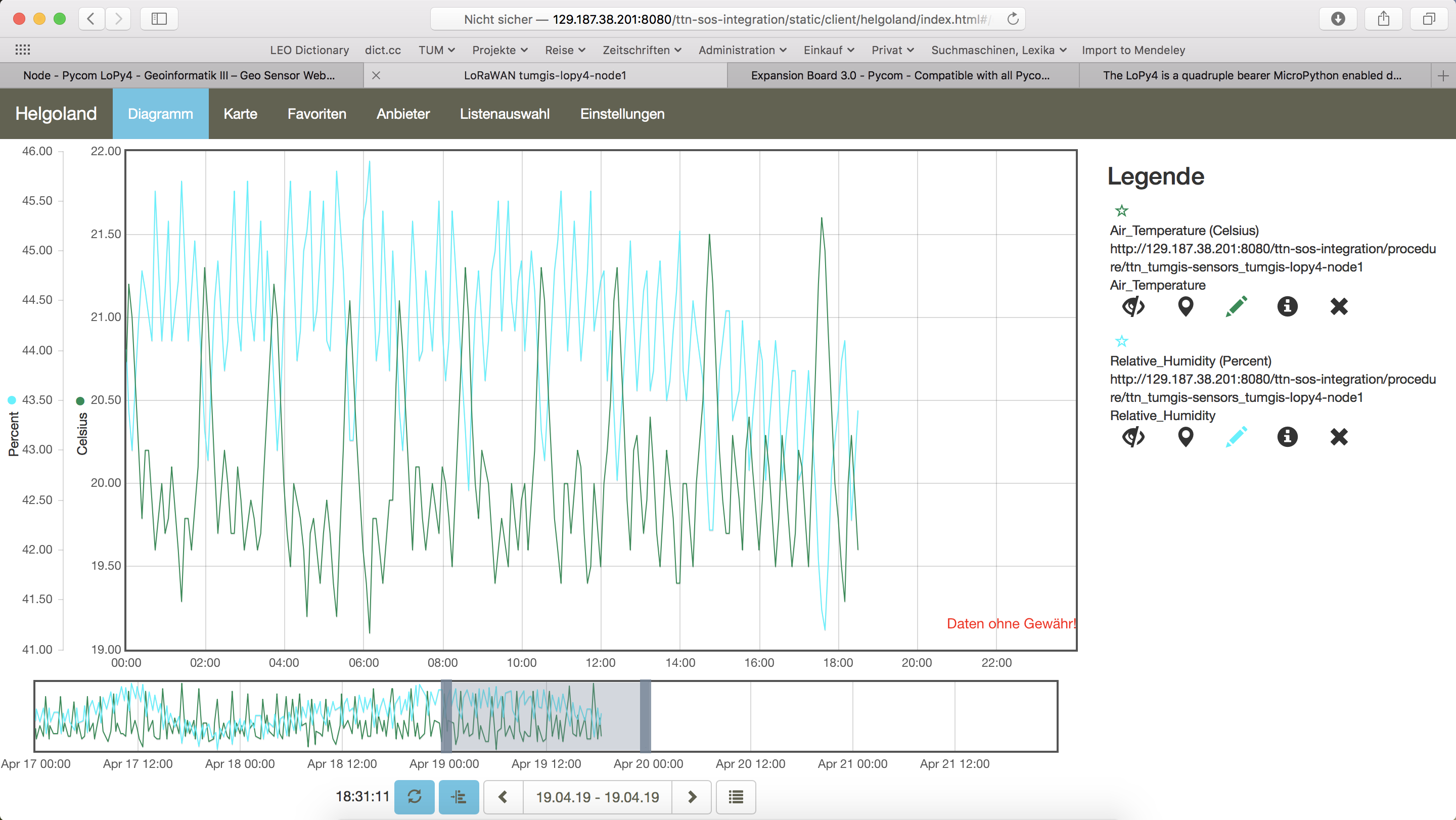
Web client for data visualization
Code files
1 2 3 4 5 6 7 8 9 10 11 12 13 14 15 16 17 18 19 20 21 22 23 24 25 26 27 28 29 30 31 32 33 34 35 36 37 38 39 40 41 42 43 44 45 46 47 48 49 50 | from network import LoRa
import socket
import time
import ubinascii
import pycom
from machine import Pin
import dht22
# Initialise LoRa in LORAWAN mode.
# Please pick the region that matches where you are using the device:
# Asia = LoRa.AS923
# Australia = LoRa.AU915
# Europe = LoRa.EU868
# United States = LoRa.US915
lora = LoRa(mode=LoRa.LORAWAN, region=LoRa.EU868)
# Create the OTAA authentication parameters:
# directly copy the values from the Things Network Console and replace the
# xxxx's and yyyy's by these values (do not prepend anything like '0x' or similar)
app_eui = ubinascii.unhexlify('xxxxxxxxxxxxxxxx')
app_key = ubinascii.unhexlify('yyyyyyyyyyyyyyyyyyyyyyyyyyyyyyyy')
print("Initializing DHT22 Sensor... ",end='')
dht = dht22.device(Pin.exp_board.G22)
print("ready!\n")
pycom.heartbeat(False)
pycom.rgbled(0xFF0000)
# join a network using OTAA (Over the Air Activation)
lora.join(activation=LoRa.OTAA, auth=(app_eui, app_key), timeout=0)
# wait until the module has joined the network
while not lora.has_joined():
time.sleep(2.5)
print('Not yet joined...')
pycom.rgbled(0x00FF00)
time.sleep(1)
# create a LoRa socket
s = socket.socket(socket.AF_LORA, socket.SOCK_RAW)
# set the LoRaWAN data rate
s.setsockopt(socket.SOL_LORA, socket.SO_DR, 5)
# set the LoRaWAN port number for transmitted packets
s.bind(7)
pycom.heartbeat(True)
|
1 2 3 4 5 6 7 8 9 10 11 12 13 14 15 16 17 18 19 20 21 22 23 24 25 26 27 28 29 30 31 32 33 34 35 36 37 38 39 40 41 42 43 44 45 46 47 48 49 50 51 52 53 54 55 56 57 58 59 60 61 | from network import LoRa
import socket
import time
import ubinascii
import pycom
from machine import Pin
import dht22
while (True):
pycom.heartbeat(False)
pycom.rgbled(0x800000)
# start a new measurement (taking 2 seconds) to ensure that the next
# retrieval of readings has current values
dht.trigger()
time.sleep(0.2)
# now start a 2nd measurements which - according to the DHT22 datasheet -
# delivers the measured values from the previous reading
hasreading=False
numtrials=0
while(not hasreading):
hasreading=dht.trigger()
numtrials=numtrials+1
if hasreading:
print("RH = {}% T = {}C".format(dht.humidity, dht.temperature))
else:
print(dht.status)
hum_msb=int(dht.humidity*100/256)
hum_lsb=int(dht.humidity*100%256)
tmp_int=int(dht.temperature*100)
# if temperature value is negative, then represent it by its 2's complement (16 bit)
if (tmp_int<0):
tmp_int=65536+tmp_int
tmp_msb=int(tmp_int/256)
tmp_lsb=int(tmp_int%256)
print("RH = {} {} T = {} {}".format(hum_msb, hum_lsb, tmp_msb, tmp_lsb))
pycom.rgbled(0x000040)
# make the socket blocking
# (waits for the data to be sent and for the 2 receive windows to expire)
s.setblocking(True)
# send some data
s.send(bytes([tmp_msb, tmp_lsb, hum_msb, hum_lsb, 0, 0]))
# make the socket non-blocking
# (because if there's no data received it will block forever...)
s.setblocking(False)
# get any data received (if any...)
data = s.recv(64)
print(data)
pycom.heartbeat(True)
# wait for such a time period that we have one measurement every 300 seconds
time.sleep(300-numtrials*4-3)
|
1 2 3 4 5 6 7 8 9 10 11 12 13 14 15 16 17 18 19 20 21 22 23 24 25 26 27 28 29 30 31 32 33 34 35 36 37 38 39 40 41 42 43 44 45 46 47 48 49 50 51 52 53 54 55 56 57 58 59 60 61 62 63 64 65 66 67 68 69 70 71 72 73 |
# dht22.py
#
# Class file for accessing the DHT22 temperature and humidity sensor using a WiPy 2.0.
#
# 2018 - Erik de Lange

from machine import Pin

import pycom
import time

class device:

    def __init__(self, pin):
        self.temperature = None
        self.humidity = None
        self.status = "NoConversionStartedError"
        self.pin = Pin(pin, mode=Pin.OPEN_DRAIN)

    def trigger(self):
        self.pin(1)
        time.sleep(2)  # enforce two second read interval

        self.pin(0)  # send start signal (1ms low).
        time.sleep_ms(1)

        pulses = pycom.pulses_get(self.pin, 100)  # capture communication

        self.pin.init(Pin.OPEN_DRAIN)

        if len(pulses) != 82:  # 40 data bit plus one acknowledge expected
            self.status = "ReadError - received {} only pulses".format(len(pulses))
            return False

        bits = []

        for level, duration in pulses[1:]:
            if level == 1:
                bits.append(0 if duration < 50 else 1)  # convert to 0 or 1

        data = []

        for n in range(5):
            byte = 0
            for i in range(8):  # shift 8 bits into a byte
                byte <<= 1
                byte += bits[n * 8 + i]
            data.append(byte)

        int_rh, dec_rh, int_t, dec_t, csum = data

        if ((int_rh + dec_rh + int_t + dec_t) & 0xFF) != csum:
            self.status = "Checksum Error"
            return False

        self.humidity = ((int_rh * 256) + dec_rh) / 10
        self.temperature = (((int_t & 0x7F) * 256) + dec_t) / 10
        if (int_t & 0x80) > 0:
            self.temperature *= -1

        self.status = "OK"
        return True


if __name__ == "__main__":
    dht = device(Pin.exp_board.G22)

    for _ in range(5):
        if dht.trigger() == True:
            print("RH = {}%  T = {}C".format(dht.humidity, dht.temperature))
        else:
            print(dht.status)
|
1 2 3 4 5 6 7 8 9 10 11 12 13 14 15 16 17 18 19 20 21 22 23 24 25 26 27 28 29 30 31 32 33 34 35 36 37 | function Decoder (bytes, port) {
var result = {};
var transformers = {};
if (port==7) {
transformers = {
'temperature': function transform (bytes) {
value=bytes[0]*256 + bytes[1];
if (value>=32768) value=value-65536;
return value/100.0;
},
'humidity': function transform (bytes) {
return (bytes[0]*256 + bytes[1])/100.0;
},
'vbattery': function transform (bytes) {
return (bytes[0]*256 + bytes[1])/100.0;
},
}
result['temperature'] = {
value: transformers['temperature'](bytes.slice(0, 2)),
uom: 'Celsius',
}
result['humidity'] = {
value: transformers['humidity'](bytes.slice(2, 4)),
uom: 'Percent',
}
result['vbattery'] = {
value: transformers['vbattery'](bytes.slice(4, 6)),
uom: 'Volt',
}
}
return result;
}
|
References
- Pycom LoPy4 product homepage
- LoPy4 specification document
- LoPy4 pinout specification
- LoPy4 online documentation (incl. description of software libraries)
- MicroPython language and library reference
- LoPy4 Getting Started (hardware & software setup, installation of Pymakr IDE)
On the Expansion Board 3.0
On the DHT22 sensor