Dragino LoRa Arduino Shield
This tutorial is made to showcase the use of Dragino LoRa Arduino board to create a LoRaWAN enabled sensor node. In the following example, a temperature and humidity sensor was used with the Dragino LoRa board.
Hardware
Microcontroller
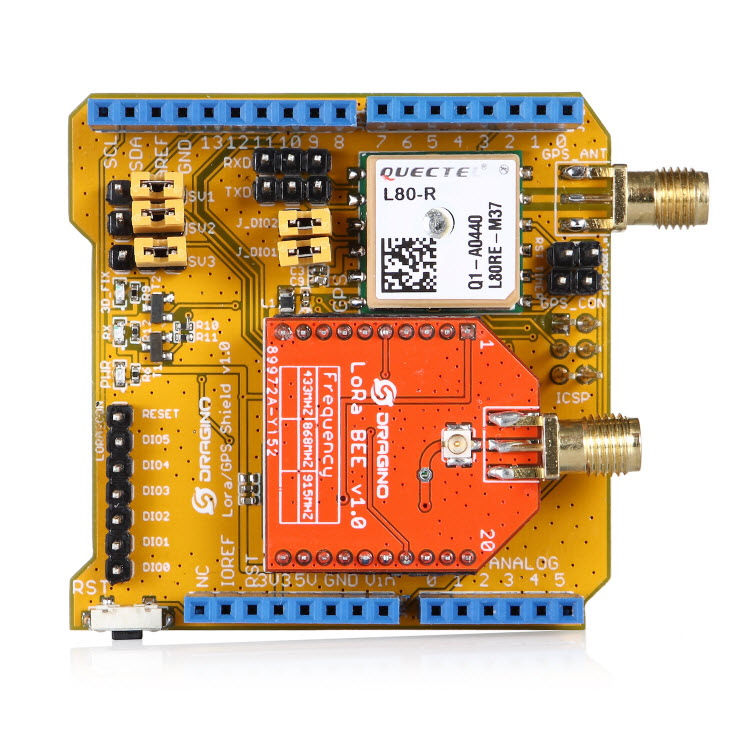
LoRa/GPS Shield from Dragino. LoRa/GPS Shield Wiki with explanations, datasheets, and examples.
The employed microcontroller board is an Arduino Uno R3 variant (i.e. it is a cheap clone of the Arduino Uno R3). It is operated by the 8bit ATmega328 microcontroller running at 16MHz. It has 32 KB flash memory (to store the program code), 1 KB EEPROM (to store configuration data), and 2 KB of RAM (to store variables, status information, and buffers). The operating voltage of the board is 5V (this is important when attaching sensors and other peripherals; they also must operate on 5V). The board offers 20 general purpose digital input/output pins (20 GPIOs) of which 6 can be used as analog input pins (with 10bit analog digital converters (ADC)) and 6 as PWM outputs, one serial port (programmable Universal Asynchronous Receiver and Transmitter, UART), one I2C port, one SPI port, one USB port (which is attached to a USB/Serial converter that is connected to the hardware serial port). Arduino Uno R3 compatible boards are available in German shops from around 5 € to 10 €. The original Arduino Uno R3 board costs around 22 €.
The Dragino LoRa/GPS Shield runs on 5V and is directly attached to the connectors of the Arduino Uno R3 microcontroller board. It comes with a built-in LoRa transmitter and receiver chip SX1276 from the company Semtech that is dedicated to the 868 MHz frequency band. The SX1276 module is connected via SPI interface to the microcontroller. For that purpose, Lora CLK, Lora D0, and Lora DI must be jumpered to SCK, MISO, and MOSI respectively (on the left side of the Dragino shield when looking on the top side of the shield with the Antenna connectors showing to the right). Lora DIO1 and Lora DIO2 must be jumpered to Arduino Digital Pin 6 and Pin 7 respectively. Since the module only implements the LoRa physical layer, the LoRaWAN protocol stack must be implemented in software on the microcontroller. We are using the Arduino library LMIC for that purpose (see below). The implemented LoRaWAN functionality is compatible with LoRaWAN Class A/C.
The board also contains a Quectel L80 GPS module (based on the MTK MT3339 GPS receiver) with a built-in antenna. According to the Dragino Wiki “this GPS module can calculate and predict orbits automatically using the ephemeris data (up to 3 days) stored in internal flash memory, so the shield can fix position quickly even at indoor signal levels with low power consumption”. The GPS module has a serial UART interface that can be connected in different ways to the Arduino microcontroller. The default data transmission rate is 9600 baud, the default position reporting rate is 1s (1 Hz). The module is capable to report up to 10 positions per second (10 Hz). Supported protocols are NMEA 0183 and MediaTek PMTK. Note that the ATmega328 microcontroller has only one hardware serial UART interface and this is already connected via a USB/Serial converter to the USB port of the Arduino board. In order to attach the serial interface of the GPS module to the microcontroller two general purpose IO lines (GPIOs) are being used and the serial protocol is implemented in software. The GPS_RXD pin on the Dragino Shield must be connected to Arduino Digital Pin 4 and the GPS_TXD pin to Digital Pin 3 using two wires. No jumpers must be present for GPS_RXD and GPS_TXD (besides the two wires mentioned above to Digital Pins 4 and 3). The Dragino LoRa/GPS Shield is available in German shops for around 34 € to 40 €.
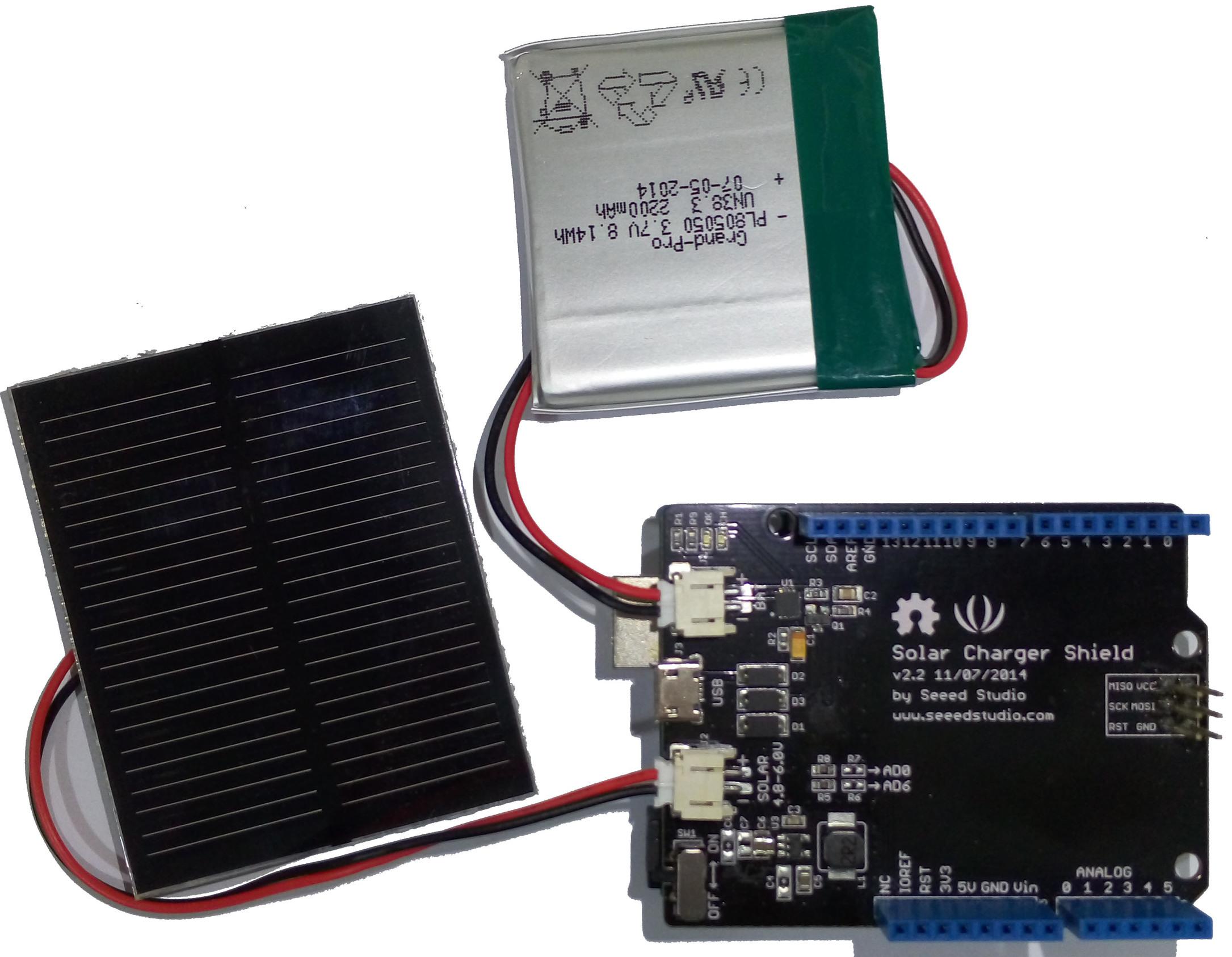
Since the Arduino Uno R3 board normally has to be powered externally via the USB port or the power connector, we have added the Solar Charger Shield V2.2 from the company Seeedstudio. This shield is directly attached to the connectors of the Arduino Uno R3 microcontroller board and sits in-between the Arduino board (bottom) and the LoRa/GPS Shield (top). A lithium polymer LiPo battery with 3.7V can be attached to the shield. The 3.7V of the battery is transformed to 5V as required by the Arduino microcontroller board. The battery is automatically recharged when the Arduino board is powered externally (over USB or the power connector). Also a photovoltaic panel with 4.8-6V can be attached to the shield to recharge the battery. The Solar Charger Shield V2.2 can report the current battery voltage level. For that purpose we had to solder a bridge on the shield at the connector marked as ‘R7’. Over a voltage divider the battery anode is connected to Analog Pin A0 and can be queried using the built-in analog/digital converter. The Solar Charger Shield V2.2 is available in German shops for around 12 € to 18 €.
Sensor
We have attached a DHT22 sensor to the microcontroller board, which measures air temperature and humidity. The minimal time interval between two measurements is 2 seconds. All data transfers between the DHT22 and the microcontroller use a single digital line. The sensor data pin is attached to a GPIO pin (here: Digital Pin 5) of the microcontroller. In addition, a so-called pull-up resistor of 4.7k to 10k Ohm must be connected between the data line and VCC (+3.3V). The DHT22 datasheet provides more technical details about the DHT22 Sensor. A tutorial on how to use the DHT22 sensor with Arduino microcontrollers is provided here. The sensor is available in German shops for around 4 € to 10 €.
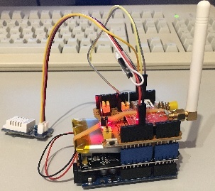
The Arduino Uno R3 (bottom) with attached Solar Charger Shield and a 2000 mAh lithium polymer LiPo battery (middle), the Dragino LoRa/GPS Shield with attached antenna (top), and an attached DHT22 temperature / humidity sensor (white box on the left).
Software
The sensor node has been programmed using the Arduino IDE. Please note, that in the Arduino framework a program is called a ‘Sketch’.
After the sketch has successfully established a connection to The Things Network it reports the air temperature, humidity, and the voltage of a (possibly) attached LiPo battery every 5 minutes. All three values are being encoded in two byte integer values each (in most significant byte order) and then sent as a 6 bytes data packet to the respective TTN application using LoRaWAN port 7. Please note, that LoRaWAN messages can be addressed to ports 1-255 (port 0 is reserved); these ports are similar to port numbers 0-65535 when using the Internet TCP/IP protocol. Voltage and humidity values are always greater or equal to 0, but the temperature value can also become negative. Negative values are represented as a two’s complement; this must be considered in the Payload Decoding Function used in The Things Network (see this section).
The next eight bytes contain two 32 bit integer values (MSB) for latitude and longitude . In order to a) provide enough precision and b) avoid negative values, the original angles (given as decimal fractions) are first added with an offset (90.0 degrees for the latitude and 180.0 degrees for the longitude) and then multiplied by 1,000,000. These transformations have to be reverted in the Payload Decoding Function. The next two bytes represent a 16 bit integer value for the altitude (MSB). The next byte contains the current number of satellites seen by the GPS receiver. Note that only when this number is greater or equal to 4 the provided GPS position is a current one. Finally, the last two bytes contain a 16 bit integer value (MSB) for the battery voltage in centivolts (this value will be divided by 100 in the Payload Decoding Function to provide volts). The entire data packet is sent to the respective TTN application using LoRaWAN port 9. Please note, that LoRaWAN messages can be addressed to ports 1-255 (port 0 is reserved); these ports are similar to port numbers 0-65535 when using the Internet TCP/IP protocol.
Currently we are not making use of the sleep mode, because we have to find out how to deal with the GPS receiver in conjunction with deep sleep mode. This means that the board is constantly drawing a significant amount of power reducing battery life considerably. Using the current sketch the sensor node can operate roughly 6 hours on battery power before it has to be recharged. Besides software improvements there are also other possibilities to reduce power consumption: the Arduino board and the Dragino LoRa/GPS Shield have power LEDs which are constantly lit during operation. Furthermore, the Dragino LoRa/GPS Shield has an indicator LED that blinks when the GPS module is successfully receiving position fixes. These LEDs could be desoldered to reduce the energy consumption of the sensor node.
The employed SX1276 LoRa module on the Dragino LoRa/GPS shield does not provide built-in support of the LoRaWAN protocol. Thus, it has to be implemented on the ATmega328 microcontroller. We use the IBM LMIC (LoraMAC-in-C) library for Arduino, which can be downloaded from this repository. Since the ATmega328 microcontroller only has 32 KB of flash memory and the LMIC library is taking most of it, there is only very limited code space left for the application dealing with the sensors (about 2 KB). Nevertheless, this is sufficient to query some sensors like in our example the DHT22 and to decode the GPS data. The source code is given in the following section: Arduino Sketch for Dragino LoRa sensor node
Services
The services used for this sensor-node are:
- TheThingsNetwork service for LoRaWAN network service.
- TheThingNetwork- OGC SensorWeb Integration
Registration of the sensor node with The Things Network (TTN)
The LoRaWAN protocol makes use of a number of different identifiers, addresses, keys, etc. These are required to unambiguously identify devices, applications, as well as to encrypt and decrypt messages. The names and meanings are nicely explained on a dedicated TTN web page.
The sketch given above connects the sensor node with The Things Network (TTN) using the Activation-by-Personalisation (ABP) mode. In this mode, the required keys for data encryption and session management are created manually using the TTN console window and must be pasted into the source code of the sketch below. In order to get this running, you will need to create a new device in the TTN console window. This assumes that you already have a TTN user account (which needs to be created otherwise). In the settings menu of the newly created device the ABP mode must be selected and the settings must be saved. Then copy the DevAddr, the NwkSKey, and in the AppSKey from the TTN console web page of the newly registered device and paste them into the proper places in the sketch above. Please make sure that you choose for each of the three keys the correct byte ordering (MSB for all three keys). A detailed explanation of these steps is given here. Then the sketch can be compiled and uploaded to the Arduino Uno R3 microcontroller.
Important hint: everytime the sensor node is reset or being started again, make sure to reset the frame counter of the registered sensor in the TTN console web page of the registered device. The reason is that in LoRaWAN all transmitted data packets have a frame counter, which is incremented after each data frame being sent. This way a LoRaWAN application can avoid receiving and using the same packet again (replay attack). When TTN receives a data packet, it checks if the frame number is higher than the last one received before. If not, the received packet is considered to be old or a replay attack and is discarded. When the sensor node is reset or being started again, its frame counter is also reset to 0, hence, the TTN application assumes that all new packages are old, because their frame counter is lower than the last frame received (before the reset). A manual frame counter reset is only necessary when registering the node using ABP mode. In OTAA mode the frame counter is automatically reset in the sensor node and the TTN network server.
TTN Payload Decoding
Everytime a data packet is received by a TTN application a dedicated Javascript function is being called (TTN payload decoder for Dragino LoRa sensor node). This function can be used to decode the received byte string and to create proper Javascript objects or values that can directly be read by humans when looking at the incoming data packet. This is also useful to format the data in a specific way that can then be forwarded to an external application (e.g. a sensor data platform like MyDevices or Thingspeak ). Such a forwarding can be configured in the TTN console in the “Integrations” tab. The Payload Decoder Function given below checks if a packet was received on LoRaWAN port 9 and then assumes that it consists of the 17 bytes encoded as described above. It creates the seven Javascript objects ‘temperature’, ‘humidity’, ‘lat’, ‘lon’, ‘altitude’, ‘sat’, and ‘vbattery’. Each object has two fields: ‘value’ holds the value and ‘uom’ gives the unit of measure. The source code can simply be copied and pasted into the ‘decoder’ tab in the TTN console after having selected the application. Choose the option ‘Custom’ in the ‘Payload Format’ field. Note that when you also want to handle other sensor nodes sending packets on different LoRaWAN ports, then the Payload Decoder Function can be extended after the end of the if (port==9) {…} statement by adding else if (port==7) {…} else if (port==8) {…} etc.
The Things Network - OGC SensorWeb Integration
The presented Payload Decoder Function works also with the TTN-OGC SWE Integration for the 52° North Sensor Observation Service (SOS). This software component can be downloaded from this repository. It connects a TTN application with a running transactional Sensor Observation Service 2.0.0 (SOS). Data packets received from TTN are imported into the SOS. The SOS persistently stores sensor data from an arbitrary number of sensor nodes and can be queried for the most recent as well as for historic sensor data readings. The 52° North SOS comes with its own REST API and a nice web client allowing to browse the stored sensor data in a convenient way.
We are running an instance of the 52° North SOS and the TTN-OGC SWE Integration. The web client for this LoRaWAN sensor node can be accessed on this page. Here is a screenshot showing the webclient:
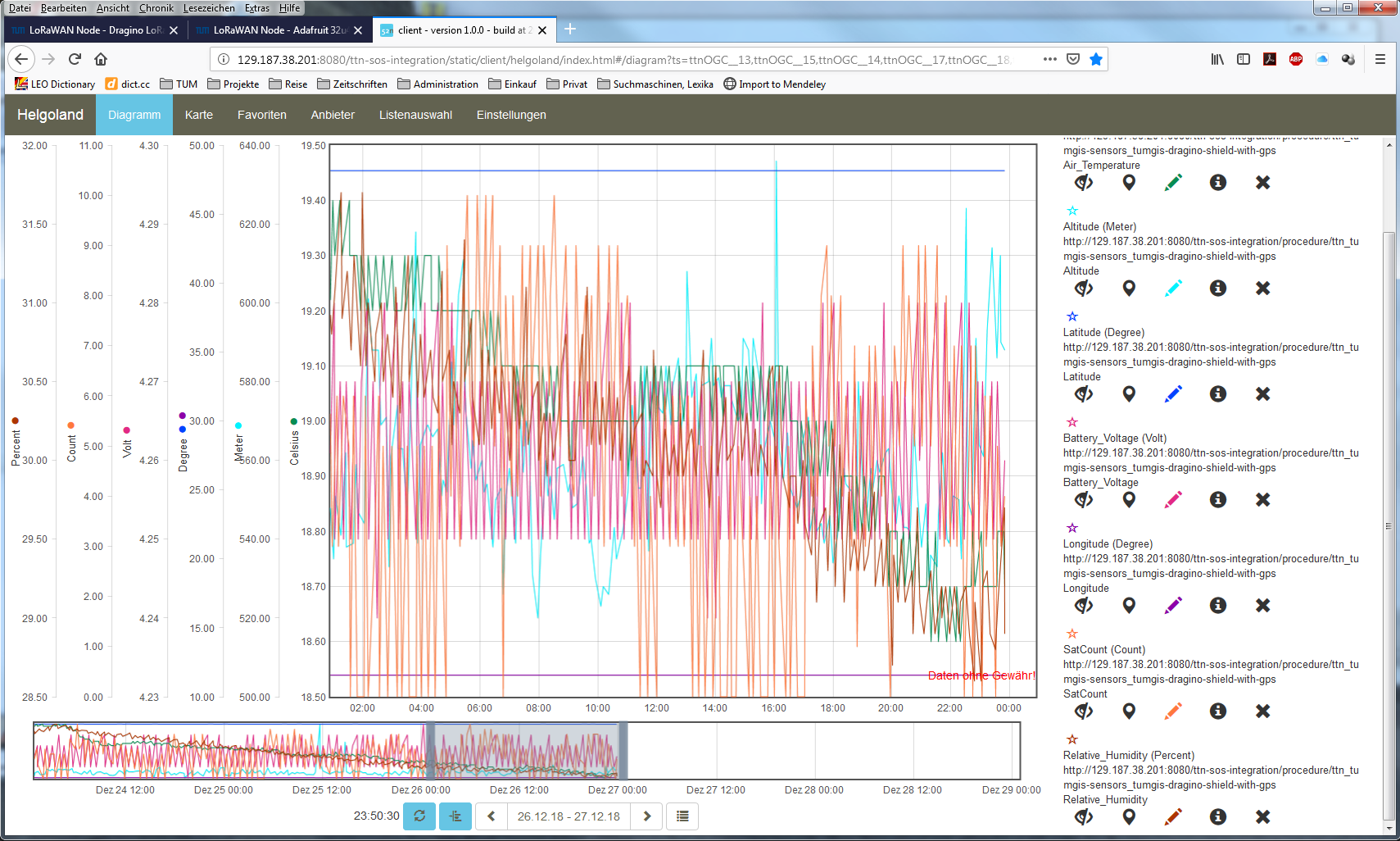
Web client for data visualization
Code files
1 2 3 4 5 6 7 8 9 10 11 12 13 14 15 16 17 18 19 20 21 22 23 24 25 26 27 28 29 30 31 32 33 34 35 36 37 38 39 40 41 42 43 44 45 46 47 48 49 50 51 52 53 54 55 56 57 58 59 60 61 62 63 64 65 66 67 68 69 70 71 72 73 74 75 76 77 78 79 80 81 82 83 84 85 86 87 88 89 90 91 92 93 94 95 96 97 98 99 100 101 102 103 104 105 106 107 108 109 110 111 112 113 114 115 116 117 118 119 120 121 122 123 124 125 126 127 128 129 130 131 132 133 134 135 136 137 138 139 140 141 142 143 144 145 146 147 148 149 150 151 152 153 154 155 156 157 158 159 160 161 162 163 164 165 166 167 168 169 170 171 172 173 174 175 176 177 178 179 180 181 182 183 184 185 186 187 188 189 190 191 192 193 194 195 196 197 198 199 200 201 202 203 204 205 206 207 208 209 210 211 212 213 214 215 216 217 218 219 220 221 222 223 224 225 226 227 228 229 230 231 232 233 234 235 236 237 238 239 240 241 242 243 244 245 246 247 248 249 250 251 252 253 254 255 256 257 258 259 260 261 262 263 264 265 266 267 268 269 270 271 272 273 274 275 276 277 278 279 280 281 282 283 284 285 286 287 288 289 290 291 292 293 294 295 296 297 298 299 300 301 302 303 304 305 306 307 308 309 310 311 312 313 314 315 316 317 318 319 320 321 322 323 324 325 326 327 328 329 330 331 332 333 334 335 336 337 338 339 340 341 342 343 344 345 346 347 348 349 350 351 352 353 354 355 356 357 358 359 360 361 362 363 364 365 366 367 368 369 370 371 372 373 374 375 376 377 378 379 380 381 382 383 384 385 386 387 388 389 390 391 392 393 394 395 396 397 398 399 400 401 402 403 404 405 406 407 408 409 410 411 412 413 414 415 416 417 418 419 420 421 422 423 424 425 426 427 428 429 430 431 432 433 434 435 436 437 438 439 440 441 442 443 444 445 446 447 448 449 450 451 452 453 454 455 456 457 458 459 460 461 462 463 464 465 466 467 468 469 470 471 472 473 474 475 476 477 478 479 480 481 482 483 484 485 486 487 488 489 490 491 492 493 494 495 496 497 498 499 500 501 502 503 504 505 506 507 508 509 510 511 512 513 514 515 516 517 518 519 520 521 522 523 524 525 526 527 528 529 530 531 532 533 534 535 536 537 538 539 540 541 542 543 544 545 546 547 548 549 550 551 552 553 554 555 556 557 558 559 560 561 562 563 564 565 566 567 568 569 570 571 572 573 574 575 576 577 578 579 580 581 582 583 584 | /*******************************************************************************
* Arduino Sketch for a LoRaWAN sensor node that is registered with
* 'The Things Network' (TTN) www.thethingsnetwork.org
*
* Author: Thomas H. Kolbe, thomas.kolbe@tum.de
* Version: 0.4
* Last update: 2018-11-28
*
* The sensor node is based on the Arduino Uno3 microcontroller board
* and the Dragino Lora Shield with GPS receiver. Also a Seeedstudio
* Solar Charger Shield V2.2 is connected to provide a battery power
* supply with the possibility to use a small PV panel for recharging.
* See https://wiki.dragino.com/index.php?title=Lora/GPS_Shield
* and http://wiki.seeedstudio.com/Solar_Charger_Shield_V2.2/
*
* The sensor node uses a DHT22 sensor measuring air temperature and humidity.
* The GPS receiver of the Dragino Lora Shield is used to locate the node.
* The voltage of an attached LiPo battery is monitored and sent as an
* additional observation.
*
* All three values are encoded as 2 byte integer values each.
* Hence, the total message payload is 6 bytes. Before the values are converted
* to integers they are multiplied by 100 to preserve 2 digits after the decimal
* point. Thus, the received values must be divided by 100 to obtain the measured
* values. The payload is sent every 60s to LoRaWAN port 9. The following
* Javascript function can be used as a payload decoding function in TTN:
*
* function Decoder(bytes, port) {
* // Decode an uplink message from a buffer
* // (array) of bytes to an object of fields.
* if (port==7) {
* var decoded = {
* "temperature": (bytes[0] << 8 | bytes[1]) / 100.0,
* "humidity": (bytes[2] << 8 | bytes[3]) / 100.0,
* "vbattery": (bytes[4] << 8 | bytes[5]) / 100.0
* };
* } else {
* var decoded = null;
* }
* return decoded;
* }
*
* In between two data transmissions the microcontroller board can go
* into sleep mode to reduce energy consumption for extended operation
* time when running on battery. Usage of the sleep mode must be
* explicitly configured below.
*
* Important hint: everytime the sensor node is reset or being started again,
* make sure to reset the frame counter of the registered sensor in the
* TTN console at https://console.thethingsnetwork.org. The reason is that
* in LoRaWAN all transmitted packets have a frame counter, which is
* incremented after each data frame being sent. This way a LoRaWAN application
* can avoid receiving and using the same packet again (replay attack). When
* TTN receives a data packet, it checks if the frame number is higher than
* the last one received before. If not, the received packet is considered
* to be old or a replay attack and is discarded. When the sensor node is
* reset or being started again, its frame counter is also reset to 0, hence,
* the TTN application assumes that all new packages are old, because their
* frame counter is lower than the last frame received (before the reset).
*
* Note, that the DHT22 data pin must be connected to Digital Pin 5 of the
* Arduino board. A resistor of 4.7k - 10k Ohm must be connected to
* the data pin and VCC (+5V). The GPS_RXD pin on the Dragiono Shield must
* be connected to Arduino Digital Pin 4 and the GPS_TXD pin to Digital Pin 3.
* Lora CLK, Lora D0, and Lora DI must be jumpered to SCK, MISO, and MOSI
* respectively (on the left side of the Dragino shield when looking on the
* top side of the shield with the Antenna connectors shwoing to the right).
* Lora DIO1 and Lora DIO2 must be jumpered to Arduino Digital Pin 6 and
* Pin 7 respectively. No jumpers must be present for GPS_RXD and GPS_TXD
* (besides the two wires mentioned above to Digital Pins 4 and 3).
*
* The code is based on the Open Source library LMIC implementing the LoRaWAN
* protocol stack on top of a given LoRa transceiver module (here: RFM95 from
* HopeRF, which uses the Semtech SX1276 LoRa chip). The library is originally
* being developed by IBM and has been ported to the Arduino platform. See
* notes below from the original developers.
*
*******************************************************************************
* Copyright (c) 2015 Thomas Telkamp and Matthijs Kooijman
*
* Permission is hereby granted, free of charge, to anyone
* obtaining a copy of this document and accompanying files,
* to do whatever they want with them without any restriction,
* including, but not limited to, copying, modification and redistribution.
* NO WARRANTY OF ANY KIND IS PROVIDED.
*
* This uses ABP (Activation-by-personalisation), where a DevAddr and
* Session keys are preconfigured (unlike OTAA, where a DevEUI and
* application key is configured, while the DevAddr and session keys are
* assigned/generated in the over-the-air-activation procedure).
*
* Note: LoRaWAN per sub-band duty-cycle limitation is enforced (1% in
* g1, 0.1% in g2), but not the TTN fair usage policy (which is probably
* violated by this sketch when left running for longer)!
*
* To use this sketch, first register your application and device with
* the things network, to set or generate a DevAddr, NwkSKey and
* AppSKey. Each device should have their own unique values for these
* fields.
*
* Do not forget to define the radio type correctly in config.h.
*
*******************************************************************************/
// If the following line is uncommented, messages are being printed out to the
// serial connection for debugging purposes. When using the Arduino Integrated
// Development Environment (Arduino IDE), these messages are displayed in the
// Serial Monitor selecting the proper port and a baudrate of 115200.
// #define SERIALDEBUG
#ifdef SERIALDEBUG
#define SERIALDEBUG_PRINT(...) Serial.print(__VA_ARGS__)
#define SERIALDEBUG_PRINTLN(...) Serial.println(__VA_ARGS__)
#else
#define SERIALDEBUG_PRINT(...)
#define SERIALDEBUG_PRINTLN(...)
#endif
// If the following line is uncommented, the sensor node goes into sleep mode
// in between two data transmissions. Also the 2secs time between the
// initialization of the DHT22 sensor and the reading of the observations
// is spent in sleep mode.
// Note, that on the Adafruit Feather 32u4 LoRa board the Serial connection
// gets lost as soon as the board goes into sleep mode, and it will not be
// established again. Thus, the definition of SERIALDEBUG should be commented
// out above when using sleep mode with this board.
// #define SLEEPMODE
#ifdef SLEEPMODE
#include <Adafruit_SleepyDog.h>
#endif
#include <lmic.h>
#include <hal/hal.h>
#include <SPI.h>
#include <DHT.h>
#define DHTPIN 5 // Arduino Digital Pin which is connected to the DHT sensor for Arduino.
#define DHTTYPE DHT22 // DHT 22 (AM2302)
DHT dht(DHTPIN, DHTTYPE); // create the sensor object
#include <TinyGPS.h>
TinyGPS gps;
bool newGPSdata = false;
#include <SoftwareSerial.h>
SoftwareSerial SWSerial(3, 4);
#define VBATPIN A0 // battery voltage is measured from Analog Input A0 for Seeed Solar Shield V2.2
// The following three constants (NwkSKey, AppSKey, DevAddr) must be changed
// for every new sensor node. We are using the LoRaWAN ABP mode (activation by
// personalisation) which means that each sensor node must be manually registered
// in the TTN console at https://console.thethingsnetwork.org before it can be
// started. In the TTN console create a new device and choose ABP mode in the
// settings of the newly created device. Then, let TTN generate the NwkSKey and
// and the AppSKey and copy them (together with the device address) from the webpage
// and paste them below.
// LoRaWAN NwkSKey, network session key
// This should be in big-endian (aka msb).
static const PROGMEM u1_t NWKSKEY[16] = {NETWORK_SESSION_KEY_HERE_IN_MSB_FORMAT};
// LoRaWAN AppSKey, application session key
// This should also be in big-endian (aka msb).
static const u1_t PROGMEM APPSKEY[16] = {APPLICATION_SESSION_KEY_HERE_IN_MSB_FORMAT};
// LoRaWAN end-device address (DevAddr)
// See http://thethingsnetwork.org/wiki/AddressSpace
// The library converts the address to network byte order as needed, so this should be in big-endian (aka msb) too.
static const u4_t DEVADDR = 0x260XXXXX ; // <-- Change this address for every node!
// These callbacks are only used in over-the-air activation, so they are
// left empty here (we cannot leave them out completely unless
// DISABLE_JOIN is set in config.h, otherwise the linker will complain).
void os_getArtEui (u1_t* buf) { }
void os_getDevEui (u1_t* buf) { }
void os_getDevKey (u1_t* buf) { }
// The following array of bytes is a placeholder to contain the message payload
// which is transmitted to the LoRaWAN gateway. We are currently only using 6 bytes.
// Please make sure to extend the size of the array, if more sensors should be
// attached to the sensor node and the message payload becomes larger than 10 bytes.
static uint8_t mydata[17] = {0, 1, 2, 3, 0, 0, 0, 0, 0, 0, 0, 0, 0, 0, 0xE, 0xF, 0x10};
static osjob_t sendjob;
// Schedule transmission every TX_INTERVAL seconds (might become longer due to duty
// cycle limitations). The total interval time is 2secs for the measurement
// plus 3secs for the LoRaWAN packet transmission plus TX_INTERVAL_AFTER_SLEEP seconds
// plus SLEEP_TIME seconds (microcontroller in sleep mode)
const unsigned TX_INTERVAL = 300; // overall cycle time (send one set of observations every 5 mins)
// const unsigned TX_INTERVAL = 30; // overall cycle time (send one set of observations every 30 secs)
const unsigned TX_TIME = 3; // rough estimate of transmission time of a single packet
const unsigned MEASURE_TIME = 2; // seconds measuring time
const unsigned SLEEP_TIME = TX_INTERVAL - TX_TIME - MEASURE_TIME;
const unsigned WAIT_TIME = TX_INTERVAL - TX_TIME - MEASURE_TIME;
// Pin mapping of the LoRa transceiver. Please make sure that DIO1 is connected
// to Arduino Digital Pin 6 using an external wire. DIO2 is left unconnected
// (it is only required, if FSK modulation instead of LoRa would be used).
const lmic_pinmap lmic_pins = {
.nss = 10,
.rxtx = LMIC_UNUSED_PIN,
.rst = 9,
.dio = {2, 6, 7},
};
void onEvent (ev_t ev) {
SERIALDEBUG_PRINT(os_getTime());
SERIALDEBUG_PRINT(": ");
switch(ev) {
case EV_SCAN_TIMEOUT:
SERIALDEBUG_PRINTLN(F("EV_SCAN_TIMEOUT"));
break;
case EV_BEACON_FOUND:
SERIALDEBUG_PRINTLN(F("EV_BEACON_FOUND"));
break;
case EV_BEACON_MISSED:
SERIALDEBUG_PRINTLN(F("EV_BEACON_MISSED"));
break;
case EV_BEACON_TRACKED:
SERIALDEBUG_PRINTLN(F("EV_BEACON_TRACKED"));
break;
case EV_JOINING:
SERIALDEBUG_PRINTLN(F("EV_JOINING"));
break;
case EV_JOINED:
SERIALDEBUG_PRINTLN(F("EV_JOINED"));
break;
case EV_RFU1:
SERIALDEBUG_PRINTLN(F("EV_RFU1"));
break;
case EV_JOIN_FAILED:
SERIALDEBUG_PRINTLN(F("EV_JOIN_FAILED"));
break;
case EV_REJOIN_FAILED:
SERIALDEBUG_PRINTLN(F("EV_REJOIN_FAILED"));
break;
case EV_TXCOMPLETE:
digitalWrite(LED_BUILTIN, LOW); // turn the LED off by making the voltage LOW
SERIALDEBUG_PRINTLN(F("EV_TXCOMPLETE (includes waiting for RX windows)"));
if (LMIC.txrxFlags & TXRX_ACK)
SERIALDEBUG_PRINTLN(F("Received ack"));
if (LMIC.dataLen) {
#ifdef SERIALDEBUG
SERIALDEBUG_PRINT(F("Received "));
SERIALDEBUG_PRINT(LMIC.dataLen);
SERIALDEBUG_PRINT(F(" bytes of payload: 0x"));
for (int i=0; i<LMIC.dataLen; i++) {
if (LMIC.frame[LMIC.dataBeg + i] < 0x10) {
SERIALDEBUG_PRINT(F("0"));
}
SERIALDEBUG_PRINT(LMIC.frame[LMIC.dataBeg + i], HEX);
}
SERIALDEBUG_PRINTLN();
#endif
// add your code to handle a received downlink data packet here
}
#ifdef SLEEPMODE
// Schedule next transmission in 1ms second after the board returns from sleep mode
os_setTimedCallback(&sendjob, os_getTime()+ms2osticks(1), do_send);
SERIALDEBUG_PRINTLN("going to sleep now ... ");
// lmic library sleeps automatically after transmission has been completed
for(int i= 0; i < SLEEP_TIME / 8; i++) {
Watchdog.sleep(8000); // maximum seems to be 8 seconds
SERIALDEBUG_PRINT('.');
}
if (SLEEP_TIME % 8) {
Watchdog.sleep((SLEEP_TIME % 8)*1000);
SERIALDEBUG_PRINT('*');
}
SERIALDEBUG_PRINTLN("... woke up again");
// We need to reset the duty cycle limits within the LMIC library.
// The reason is that in sleep mode the Arduino system timers millis and micros
// do not get incremented. However, LMIC monitors the adherence to the
// LoRaWAN duty cycle limitations using the system timers millis and micros.
// Since LMIC does not know that we have slept for a long time and duty
// cycle requirements in fact are met, we must reset the respective LMIC timers
// in order to prevent the library to wait for some extra time (which would
// not use sleep mode and, thus, would waste battery energy).
LMIC.bands[BAND_MILLI].avail = os_getTime();
LMIC.bands[BAND_CENTI].avail = os_getTime();
LMIC.bands[BAND_DECI].avail = os_getTime();
#else
// Schedule next transmission
os_setTimedCallback(&sendjob, os_getTime()+sec2osticks(WAIT_TIME), do_send);
#endif
break;
case EV_LOST_TSYNC:
SERIALDEBUG_PRINTLN(F("EV_LOST_TSYNC"));
break;
case EV_RESET:
SERIALDEBUG_PRINTLN(F("EV_RESET"));
break;
case EV_RXCOMPLETE:
// data received in ping slot
SERIALDEBUG_PRINTLN(F("EV_RXCOMPLETE"));
break;
case EV_LINK_DEAD:
SERIALDEBUG_PRINTLN(F("EV_LINK_DEAD"));
break;
case EV_LINK_ALIVE:
SERIALDEBUG_PRINTLN(F("EV_LINK_ALIVE"));
break;
default:
SERIALDEBUG_PRINTLN(F("Unknown event"));
break;
}
}
void do_send(osjob_t* j){
// Check if there is not a current TX/RX job running
if (LMIC.opmode & OP_TXRXPEND) {
SERIALDEBUG_PRINTLN(F("OP_TXRXPEND, not sending"));
} else {
// Prepare upstream data transmission at the next possible time.
float temperature, humidity, measuredvbat, lat, lon, alt;
int16_t int16_temperature, int16_humidity, int16_vbat, int16_alt;
int32_t int32_lat, int32_lon;
unsigned long age;
byte sat=0;
// Start a measurement to update the sensor's internal temperature & humidity reading.
// Note, that when fetching measurements from a DHT22 sensor, the reported
// values belong to the measurement BEFORE the current measurement.
// Therefore, in order to get current observations, we first perform a new measurement
// and wait 2 secs (which is the minimum time between two sensor observations for
// the DHT22) and then directly retrieve the observations again.
temperature = dht.readTemperature();
// temperature = 23;
#ifdef SLEEPMODE
Watchdog.sleep(2000);
#else
delay(2000);
#endif
// Now read the recently measured temperature (2 secs ago) as Celsius (the default)
temperature = dht.readTemperature();
// temperature = 23;
// Read the recently measured humidity (2 secs ago)
humidity = dht.readHumidity();
// humidity = 66;
// Check if any reads failed and exit early (to try again).
if (isnan(humidity) || isnan(temperature)) {
SERIALDEBUG_PRINTLN("Failed to read from DHT sensor!");
// blink the LED five times to indicate that the sensor values could not be read
for (int i=0; i<5; i++) {
digitalWrite(LED_BUILTIN, HIGH); // turn the LED on by making the voltage HIGH
delay(150);
digitalWrite(LED_BUILTIN, LOW); // turn the LED on by making the voltage HIGH
delay(150);
}
// ok, then wait for another period and try it again
os_setTimedCallback(&sendjob, os_getTime()+sec2osticks(TX_INTERVAL), do_send);
} else {
SERIALDEBUG_PRINT("Humidity: ");
SERIALDEBUG_PRINT(humidity);
SERIALDEBUG_PRINT(" %\t");
SERIALDEBUG_PRINT("Temperature: ");
SERIALDEBUG_PRINT(temperature);
SERIALDEBUG_PRINT(" °C ");
int16_temperature = round(100.0*temperature);
int16_humidity = round(100.0*humidity);
mydata[0] = (byte) (int16_temperature >> 8);
mydata[1] = (byte) (int16_temperature & 0x00FF);
mydata[2] = (byte) (int16_humidity >> 8);
mydata[3] = (byte) (int16_humidity & 0x00FF);
if (newGPSdata) {
gps.f_get_position(&lat, &lon, &age);
int32_lat = round(1000000.0*(lat+90.0));
int32_lon = round(1000000.0*(lon+180.0));
alt = gps.f_altitude();
int16_alt = round(alt);
sat = gps.satellites();
mydata[4] = (byte) (int32_lat >> 24);
mydata[5] = (byte) ((int32_lat >> 16) & 0x00FF);
mydata[6] = (byte) ((int32_lat >> 8) & 0x0000FF);
mydata[7] = (byte) (int32_lat & 0x000000FF);
mydata[8] = (byte) (int32_lon >> 24);
mydata[9] = (byte) ((int32_lon >> 16) & 0x00FF);
mydata[10] = (byte) ((int32_lon >> 8) & 0x0000FF);
mydata[11] = (byte) (int32_lon & 0x000000FF);
mydata[12] = (byte) (int16_alt >> 8);
mydata[13] = (byte) (int16_alt & 0x00FF);
mydata[14] = sat;
} else {
mydata[14] = 0;
}
#ifdef VBATPIN
measuredvbat = analogRead(VBATPIN);
measuredvbat *= 2.0; // we divided by 2, so multiply back
measuredvbat *= 5.0; // Multiply by 5V, our reference voltage
measuredvbat /= 1023.0; // convert to voltage
#else
measuredvbat = 0.0;
#endif
int16_vbat = round(measuredvbat * 100.0);
mydata[15] = (byte) (int16_vbat >> 8);
mydata[16] = (byte) (int16_vbat & 0x00FF);
SERIALDEBUG_PRINT(" \t");
SERIALDEBUG_PRINT("Battery Voltage: ");
SERIALDEBUG_PRINT(measuredvbat);
SERIALDEBUG_PRINTLN(" V");
// Send the 17 bytes payload to LoRaWAN port 9 and do not request an acknowledgement.
// The following call does not directly sends the data, but puts a "send job"
// in the job queue. This job eventually is performed in the call "os_runloop_once();"
// issued repeatedly in the "loop()" method below. After the transmission is
// complete, the EV_TXCOMPLETE event is signaled, which is handled in the
// event handler method "onEvent (ev_t ev)" above. In the EV_TXCOMPLETE branch
// then a new call to the "do_send(osjob_t* j)" method is being prepared for
// delayed execution with a waiting time of TX_INTERVAL seconds.
LMIC_setTxData2(9, mydata, 17, 0);
SERIALDEBUG_PRINTLN(F("Packet queued"));
newGPSdata=false;
digitalWrite(LED_BUILTIN, HIGH); // turn the LED on by making the voltage HIGH
// Next TX is scheduled after TX_COMPLETE event.
}
}
}
void setup() {
delay(5000); // give enough time to open serial monitor (if needed)
pinMode(LED_BUILTIN, OUTPUT);
digitalWrite(LED_BUILTIN, LOW); // turn the LED off by making the voltage LOW
#ifdef SERIALDEBUG
Serial.begin(115200);
// while (!Serial);
#endif
dht.begin(); // initialize DHT22 sensor
SERIALDEBUG_PRINTLN(F("Starting"));
#ifdef VCC_ENABLE
// For Pinoccio Scout boards
pinMode(VCC_ENABLE, OUTPUT);
digitalWrite(VCC_ENABLE, HIGH);
delay(1000);
#endif
SWSerial.begin(9600);
// LMIC init
os_init();
// Reset the MAC state. Session and pending data transfers will be discarded.
LMIC_reset();
LMIC_setClockError(MAX_CLOCK_ERROR * 1 / 100);
// Set static session parameters. Instead of dynamically establishing a session
// by joining the network, precomputed session parameters are be provided.
#ifdef PROGMEM
// On AVR, these values are stored in flash and only copied to RAM
// once. Copy them to a temporary buffer here, LMIC_setSession will
// copy them into a buffer of its own again.
uint8_t appskey[sizeof(APPSKEY)];
uint8_t nwkskey[sizeof(NWKSKEY)];
memcpy_P(appskey, APPSKEY, sizeof(APPSKEY));
memcpy_P(nwkskey, NWKSKEY, sizeof(NWKSKEY));
LMIC_setSession (0x1, DEVADDR, nwkskey, appskey);
#else
// If not running an AVR with PROGMEM, just use the arrays directly
LMIC_setSession (0x1, DEVADDR, NWKSKEY, APPSKEY);
#endif
#if defined(CFG_eu868)
// Set up the channels used by the Things Network, which corresponds
// to the defaults of most gateways. Without this, only three base
// channels from the LoRaWAN specification are used, which certainly
// works, so it is good for debugging, but can overload those
// frequencies, so be sure to configure the full frequency range of
// your network here (unless your network autoconfigures them).
// Setting up channels should happen after LMIC_setSession, as that
// configures the minimal channel set.
// NA-US channels 0-71 are configured automatically
LMIC_setupChannel(0, 868100000, DR_RANGE_MAP(DR_SF12, DR_SF7), BAND_CENTI); // g-band
LMIC_setupChannel(1, 868300000, DR_RANGE_MAP(DR_SF12, DR_SF7B), BAND_CENTI); // g-band
LMIC_setupChannel(2, 868500000, DR_RANGE_MAP(DR_SF12, DR_SF7), BAND_CENTI); // g-band
LMIC_setupChannel(3, 867100000, DR_RANGE_MAP(DR_SF12, DR_SF7), BAND_CENTI); // g-band
LMIC_setupChannel(4, 867300000, DR_RANGE_MAP(DR_SF12, DR_SF7), BAND_CENTI); // g-band
LMIC_setupChannel(5, 867500000, DR_RANGE_MAP(DR_SF12, DR_SF7), BAND_CENTI); // g-band
LMIC_setupChannel(6, 867700000, DR_RANGE_MAP(DR_SF12, DR_SF7), BAND_CENTI); // g-band
LMIC_setupChannel(7, 867900000, DR_RANGE_MAP(DR_SF12, DR_SF7), BAND_CENTI); // g-band
LMIC_setupChannel(8, 868800000, DR_RANGE_MAP(DR_FSK, DR_FSK), BAND_MILLI); // g2-band
// TTN defines an additional channel at 869.525Mhz using SF9 for class B
// devices' ping slots. LMIC does not have an easy way to define set this
// frequency and support for class B is spotty and untested, so this
// frequency is not configured here.
#elif defined(CFG_us915)
// NA-US channels 0-71 are configured automatically
// but only one group of 8 should (a subband) should be active
// TTN recommends the second sub band, 1 in a zero based count.
// https://github.com/TheThingsNetwork/gateway-conf/blob/master/US-global_conf.json
LMIC_selectSubBand(1);
#endif
// Disable link check validation
LMIC_setLinkCheckMode(0);
// TTN uses SF9 for its RX2 window.
LMIC.dn2Dr = DR_SF9;
// Set data rate and transmit power for uplink (note: txpow seems to be ignored by the library)
// LMIC_setDrTxpow(DR_SF7,14);
LMIC_setDrTxpow(DR_SF9,14);
// Start job. This will initiate the repetitive sending of data packets,
// because after each data transmission, a delayed call to "do_send()"
// is being scheduled again.
do_send(&sendjob);
}
void loop() {
/*
// read from port 1, send to port 0:
if (Serial.available()) {
int inByte = Serial.read();
SWSerial.write(inByte);
}
// read from port 0, send to port 1:
if (SWSerial.available()) {
int inByte = SWSerial.read();
Serial.write(inByte);
}
*/
unsigned long chars;
unsigned short sentences, failed;
// For one second we parse GPS data and report some key values
// for (unsigned long start = millis(); millis() - start < 1000;)
// {
while (SWSerial.available())
{
char c = SWSerial.read();
// Serial.write(c); // uncomment this line if you want to see the GPS data flowing
if (gps.encode(c)) // Did a new valid sentence come in?
newGPSdata = true;
}
// }
/*
if (newGPSdata)
{
float flat, flon;
unsigned long age;
gps.f_get_position(&flat, &flon, &age);
Serial.print("LAT=");
Serial.print(flat == TinyGPS::GPS_INVALID_F_ANGLE ? 0.0 : flat, 6);
Serial.print(" LON=");
Serial.print(flon == TinyGPS::GPS_INVALID_F_ANGLE ? 0.0 : flon, 6);
Serial.print(" ALT=");
Serial.print(gps.f_altitude() == TinyGPS::GPS_INVALID_F_ALTITUDE ? 0.0 : gps.f_altitude(), 6);
Serial.print(" SAT=");
Serial.print(gps.satellites() == TinyGPS::GPS_INVALID_SATELLITES ? 0 : gps.satellites());
Serial.print(" PREC=");
Serial.print(gps.hdop() == TinyGPS::GPS_INVALID_HDOP ? 0 : gps.hdop());
}
gps.stats(&chars, &sentences, &failed);
Serial.print(" CHARS=");
Serial.print(chars);
Serial.print(" SENTENCES=");
Serial.print(sentences);
Serial.print(" CSUM ERR=");
Serial.println(failed);
if (chars == 0)
Serial.println("** No characters received from GPS: check wiring **");
*/
os_runloop_once();
}
|
1 2 3 4 5 6 7 8 9 10 11 12 13 14 15 16 17 18 19 20 21 22 23 24 25 26 27 28 29 30 31 32 33 34 35 36 37 38 39 40 41 42 43 44 45 46 47 48 49 50 51 52 53 54 55 56 57 58 59 60 61 62 63 64 65 66 67 68 69 70 71 72 73 74 75 76 77 | function Decoder(bytes, port) {
var result = {};
var transformers = {};
if (port == 9) {
transformers = {
temperature: function transform(bytes) {
value = bytes[0] * 256 + bytes[1];
if (value >= 32768) value = value - 65536;
return value / 100.0;
},
humidity: function transform(bytes) {
return (bytes[0] * 256 + bytes[1]) / 100.0;
},
lat: function transform(bytes) {
return (
(bytes[0] * 16777216 + bytes[1] * 65536 + bytes[2] * 256 + bytes[3]) /
1000000.0 -
90.0
);
},
lon: function transform(bytes) {
return (
(bytes[0] * 16777216 + bytes[1] * 65536 + bytes[2] * 256 + bytes[3]) /
1000000.0 -
180.0
);
},
altitude: function transform(bytes) {
return bytes[0] * 256 + bytes[1];
},
sat: function transform(bytes) {
return bytes[0];
},
vbattery: function transform(bytes) {
return (bytes[0] * 256 + bytes[1]) / 100.0;
}
};
result["temperature"] = {
value: transformers["temperature"](bytes.slice(0, 2)),
uom: "Celsius"
};
result["humidity"] = {
value: transformers["humidity"](bytes.slice(2, 4)),
uom: "Percent"
};
result["lat"] = {
value: transformers["lat"](bytes.slice(4, 8)),
uom: "Degree"
};
result["lon"] = {
value: transformers["lon"](bytes.slice(8, 12)),
uom: "Degree"
};
result["altitude"] = {
value: transformers["altitude"](bytes.slice(12, 14)),
uom: "Meter"
};
result["sat"] = {
value: transformers["sat"](bytes.slice(14, 15)),
uom: "Count"
};
result["vbattery"] = {
value: transformers["vbattery"](bytes.slice(15, 17)),
uom: "Volt"
};
return result;
}
}
|
References
- Arduino Uno R3 microcontroller
- FAQ on Arduino microcontrollers from Adafruit
- Dragino Lora/GPS Shield Wiki
- Dragino Lora/GPS Shield github
- Seeedstudio Solar Charger Shield V2.2
- IBM LMIC (LoraMAC-in-C) library for Arduino
- Connect to TTN - Wiki for Dragino Project
- dragino/Arduino-Profile-Examples/Arduino_LMIC.ino GitHub
- dragino/Arduino-Profile-Examples/tinygps_example.ino GitHub
- goodcheney/ttn_mapper/gps_shield at master GitHub
On battery saving / using the deep sleep mode (these are written for other microcontroller boards, but do apply for the Arduino Uno R3 and the Dragino Lora/GPS Shield, too):
- Adafruit Feather 32u4 LoRa - long transmission time after deep sleep - End Devices (Nodes) - The Things Network
- Full Arduino Mini LoraWAN and 1.3uA Sleep Mode - End Devices (Nodes) - The Things Network
- Adding Method to Adjust hal_ticks Upon Waking Up from Sleep · Issue #109 · matthijskooijman/arduino-lmic
- minilora-test/minilora-test.ino at cbe686826bd84fac8381de47b5f5b02dd47c2ca0 · tkerby/minilora-test
- Arduino-LMIC library with low power mode - Mario Zwiers