Seeeduino LoRaWAN
Hardware
Microcontroller
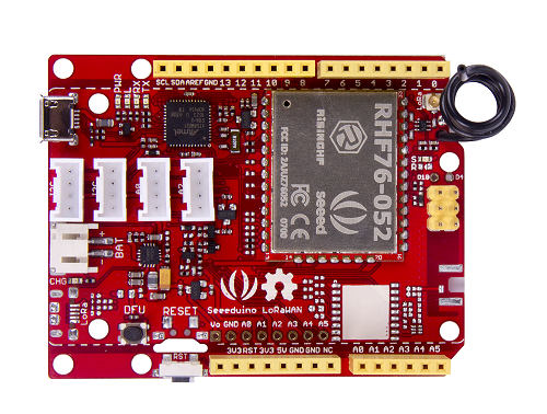
Seeeduino LoRaWAN microcontroller from Seeed Studio.
The Seeeduino LoRaWAN module is operated by the 32bit microcontroller ATSAMD21G18 (ARM® Cortex®-M0+) running at 48MHz. It has 256 KB flash memory (to store the program code) and 32 KB of RAM (to store variables, status information, and buffers). The operating voltage of the board is 3.3V (this is important when attaching sensors and other peripherals; they also must operate on 3.3V). The board offers 20 general purpose digital input/output pins (20 GPIOs), 6 analog input pins (with 12bit analog digital converters (ADC)), 1 analog output pin (with 10bit digital analog converter (DAC)), 2 serial ports (2 programmable Universal Asynchronous Receiver and Transmitters, UARTs). The board comes with an embedded lithium battery management chip and status indicator led, which allows to directly connect a 3.7V LiPo rechargeable battery that will be automatically recharged when the board is powered over its USB connector. The battery voltage level can be queried from analog input A4, the charging status (charging, full) from analog input A5. The Seeeduino LoRaWAN (without GPS module) is available in German shops for around 37 €.
The LoRa transmitter and receiver is encapsulated within an RHF76-052AM module from the Chinese company RisingHF. The RF module contains its own microcontroller, which implements the LoRaWAN protocol. The module is connected via the serial interface to the ATSAMD21G18 microcontroller and can be controlled by sending so-called ‘AT’ commands. The implemented LoRaWAN functionality is compatible with LoRaWAN Class A/C. The explanation of all supported commands as well as a number of examples on how to use the Seeeduino LoRaWAN are given on the Seeeduino LoRaWAN Wiki.
The board has 4 on-board Grove connectors. ‘Grove’ is a framework developed by the company Seeed Studio standardizing the connectors, operating voltages, and pin configurations for attaching peripherals like sensors, actuators, and displays to microcontrollers. Note that the Grove modules need to be able to operate (also) on 3.3V (instead of only with 5V), because the Seeeduino LoRaWAN board only provides 3.3V to the Grove connectors. Important hint: if you want to use the Grove ports, make sure to include the command “digitalWrite(38, HIGH)” in the setup() routine of your program. A low level on that pin deactivates the power supply of the four Grove ports.
The board has also the typical Arduino UNO connectors allowing to attach so-called Arduino shields (however, please note that the shields must be working with 3.3V; the normal operating voltage for the Arduino UNO microcontroller and its shields is 5V).
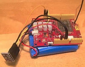
The Seeeduino LoRaWAN GPS microcontroller with a 6600 mAh lithium polymer (LiPo) battery (bottom), and an attached BME280 temperature / humidity / barometer sensor module.
Sensor
We attached a Bosch BME280 sensor module to the extension connectors of the microcontroller board using 5 wires. The employed BME280 sensor board is a cheap no-name product. VCC and GND are connected to 3.3V and GND of the microcontroller board respectively. SCL and SDA from the sensor board are connected to SCL and SDA of the microcontroller board. SDO from the sensor board is also connected to GND of the microcontroller; it selects 0x76 as the I2C device address (a high level, i.e. 3.3V, would set the device address to 0x77 - this is relevant, if two sensor modules should be operated on the same I2C bus). Note that there is also a Seeed Grove BME280 module available which alternatively can be used and connected to the first I2C Grove connector of the Seeeduino LoRaWAN board. The BME280 measures temperature in the range -40 - 85 ℃, with ±1.0°C accuracy; 0% - 100% relative humidity with ±3% accuracy; and atmospheric pressure in the range 300 - 1100 hPa (1 hPa= one hundred Pa) with ±1.0 hPa accuracy. It offers the two interface standards I2C and SPI (we are using I2C here and the default I2C address 0x76). The atmospheric pressure changes with altitude, hence, the BME280 can also be used to measure the approximate altitude of a place.
Software
The sensor node has been programmed using the Arduino IDE. Please note, that in the Arduino framework a program is called a ‘Sketch’.
In order to support the “Seeeduino LoRaWAN” board with the Arduino IDE, make sure to have installed the package “Seeed SAMD boards by Seeed Studio” in version 1.3.0 using the board manager in the Arduino IDE. This is also explained on a dedicated webpage from Seeed Studio. The sketch requires the software libraries “RTCZero”, “Arduino_BME280”, “Adafruit_Sensor”, “Wire”, and “LoRaWAN”. The first three have to be installed using the library manager of the Arduino IDE, the fourth library is already installed with the Arduino IDE and the latter library comes with the “Seeeduino LoRaWAN” board installation.
After the sketch has successfully established a connection to The Things Network it reports the air temperature, relative humidity, air pressure, altitude, and the voltage of a (possibly) attached LiPo battery every 5 minutes. All five values are being encoded in two byte integer values each and then sent as a 10 bytes data packet to the respective TTN application using LoRaWAN port 33. Please note, that LoRaWAN messages can be addressed to ports 1-255 (port 0 is reserved); these ports are similar to port numbers 0-65535 when using the Internet TCP/IP protocol. Voltage, pressure, altitude, and humidity values are always greater or equal to 0, but the temperature value can also become negative. Negative values are represented as a two’s complement; this must be considered in the Payload Decoding Function used in The Things Network (see below).
In between two sensor readings the microcontroller, the LoRaWAN module, and the sensor module are going into deep sleep mode to save battery power. During LoRaWAN data transmission the device draws up to 65mA current. When in sleep mode the entire node only draws around 0.06 mA power. Hence, with a 6600 mAh 3.7V LiPo battery and the current version of the sketch the system should be able to run for many years before recharging (not taking into account the self-discharging rate of the battery).
The source code is provided in the following section Arduino Sketch for Seeeduino LoRaWAN sensor node
Services
The services used for this sensor-node are:
- TheThingsNetwork service for LoRaWAN network service.
- TheThingsNetwork - OGC SensorWeb integration for uploading LoRaWAN sensor data into OGC infrastructure.
Registration of the sensor node with The Things Network (TTN)
The LoRaWAN protocol makes use of a number of different identifiers, addresses, keys, etc. These are required to unambiguously identify devices, applications, as well as to encrypt and decrypt messages. The names and meanings are nicely explained on a dedicated TTN web page.
The sketch given above connects the sensor node with The Things Network (TTN) using the Over-the-Air-Activation (OTAA) mode. In this mode, we use the three keys AppEUI, DevEUI, AppKey. The DevEUI should normally be delivered with the sensor node by the manufacturer. However, it seems that there is no explicit DevEUI provided with the Seeeduino LoRaWAN module. Therefore, it has to be generated automatically together with the other two keys using the TTN console. Each sensor node must be manually registered in the TTN console before it can be started. This assumes that you already have a TTN user account (which needs to be created otherwise). In the TTN console create a new device with also the DevEUI being automatically generated. After the registration of the device the respective keys (AppEUI, DevEUI, AppKey) can be copied from the TTN console and must be pasted into the the proper places in the source code of the sketch above. Please make sure that you choose for each of the three keys are in the correct byte ordering (all are in MSB, i.e. in the same ordering as given in the TTN console). A detailed explanation of these steps is given on this page. Then the sketch can be compiled and uploaded to the Seeeduino LoRaWAN microcontroller. Note that the three constants (AppEUI, DevEUI, AppKey) must be changed in the source code for every new sensor node.
Using the OTAA mode has the advantage over the ABP (activation by personalization) mode that during connection the session keys are newly created which improves security. Another advantage is that the packet counter is automatically reset to 0 both in the node and in the TTN application.
TTN Payload Decoding
Everytime a data packet is received by a TTN application a dedicated Javascript function is being called (Payload Decoder Function). This function can be used to decode the received byte string and to create proper Javascript objects or values that can directly be read by humans when looking at the incoming data packet. This is also useful to format the data in a specific way that can then be forwarded to an external application (e.g. a sensor data platform like MyDevices or Thingspeak ).
Such a forwarding can be configured in the TTN console in the “Integrations” tab. TTN payload decoder for Seeeduino LoRaWAN sensor node given here checks if a packet was received on LoRaWAN port 33 and then assumes that it consists of the 10 bytes encoded as described above. It creates the five Javascript objects ‘temperature’, ‘humidity’, ‘pressure’, ‘altitude’, and ‘vbattery’. Each object has two fields: ‘value’ holds the value and ‘uom’ gives the unit of measure. The source code can simply be copied and pasted into the ‘decoder’ tab in the TTN console after having selected the application. Choose the option ‘Custom’ in the ‘Payload Format’ field. Note that when you also want to handle other sensor nodes sending packets on different LoRaWAN ports, then the Payload Decoder Function can be extended after the end of the if (port==33) {…} statement by adding else if (port==7) {…} else if (port==8) {…} etc.
The Things Network - OGC SensorWeb Integration
The presented Payload Decoder Function works also with the TTN-OGC SWE Integration for the 52° North Sensor Observation Service (SOS). This software component can be downloaded from this repository. It connects a TTN application with a running transactional Sensor Observation Service 2.0.0 (SOS). Data packets received from TTN are imported into the SOS. The SOS persistently stores sensor data from an arbitrary number of sensor nodes and can be queried for the most recent as well as for historic sensor data readings. The 52° North SOS comes with its own REST API and a nice web client allowing to browse the stored sensor data in a convenient way.
We are running an instance of the 52° North SOS and the TTN-OGC SWE Integration. The web client for this LoRaWAN sensor node can be accessed on this webpage. Here is a screenshot showing the webclient:
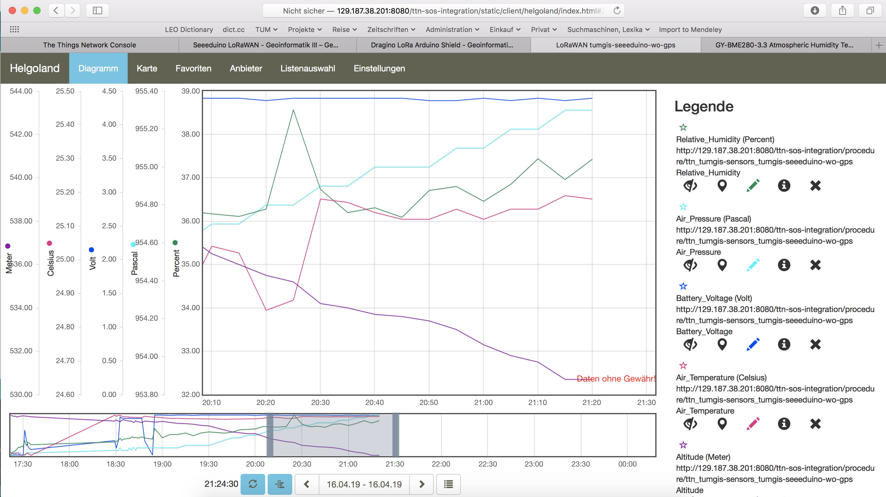
Web client for data visualization
Code files
1 2 3 4 5 6 7 8 9 10 11 12 13 14 15 16 17 18 19 20 21 22 23 24 25 26 27 28 29 30 31 32 33 34 35 36 37 38 39 40 41 42 43 44 45 46 47 48 49 50 51 52 53 54 55 56 57 58 59 60 61 62 63 64 65 66 67 68 69 70 71 72 73 74 75 76 77 78 79 80 81 82 83 84 85 86 87 88 89 90 91 92 93 94 95 96 97 98 99 100 101 102 103 104 105 106 107 108 109 110 111 112 113 114 115 116 117 118 119 120 121 122 123 124 125 126 127 128 129 130 131 132 133 134 135 136 137 138 139 140 141 142 143 144 145 146 147 148 149 150 151 152 153 154 155 156 157 158 159 160 161 162 163 164 165 166 167 168 169 170 171 172 173 174 175 176 177 178 179 180 181 182 183 184 185 186 187 188 189 190 191 192 193 194 195 196 197 198 199 200 201 202 203 204 205 206 207 208 209 210 211 212 213 214 215 216 217 218 219 220 221 222 223 224 225 226 227 228 229 230 231 232 233 234 235 236 237 238 239 240 241 242 243 244 245 246 247 248 249 250 251 252 253 254 255 256 257 258 259 260 261 262 263 264 265 266 267 268 269 270 271 272 273 274 275 276 277 278 279 280 281 282 283 284 285 286 287 288 289 290 291 292 293 294 295 296 297 | /*******************************************************************************
* Arduino Sketch for a LoRaWAN sensor node that is registered with
* 'The Things Network' (TTN) www.thethingsnetwork.org
*
* Filename: Seeeduino_LoRaWAN_GPS_BME280_OTAA_Sleep_Adafruit_V2.ino
*
* Author: Thomas H. Kolbe, thomas.kolbe@tum.de
* Version: 1.0.1
* Last update: 2019-04-17
*
* This sketch works with a Seeeduino LoRaWAN microcontroller board (with or
* without embedded GPS module). See http://wiki.seeedstudio.com/Seeeduino_LoRAWAN/
* It requires a Seeed Grove BME280 air temperature, relative humidity,
* and air pressure sensor module attached to the I2C Grove connector of
* the microcontroller board. The current configuration assumes that
* the BME280 is configured to I2C device address 0x76 (default).
* The sketch makes a connection to The Things Network (TTN) using
* LoRaWAN in OTAA mode. It then sends a data packet of 10 bytes to
* LoRaWAN port 33 around every 5 minutes. The packet contains the
* following 5 integer values (16 bit, most significant byte (MSB) first):
* 1. temperature in Celsius (signed, multiplied by 100)
* 2. relative humidity in percent (unsigned, multiplied by 100)
* 3. air pressure in Pascal (unsigned, divided by 10)
* 4. current altitude in Meters (unsigned, multiplied by 10)
* 5. battery voltage in millivolt (unsigned)
* These values have to be decoded by the LoRaWAN network controller
* using a proper "payload decoder function" written in Javascript.
*
* Note that when the board is powered over the USB connector and
* no battery is connected, the measured battery voltage is incorrect.
*
* If the board shall be running on a lithium polymer (LiPo) battery,
* it is recommended to remove the green power LED from the board or
* to cut the connection between the LED and the resistor lying above
* of it as the LED constantly draws around 8mW of power. In order to
* save energy the sketch puts the GPS module on the board to standby
* mode right from the beginning. After each measurement and data transfer
* the LoRaWAN module and the sensor is put to standby mode, too, and the
* microcontroller goes into deep sleep mode. All components require
* a total current of around 0.34mA during sleep mode and up to 65mA
* during LoRa transmission for the board version with GPS. The board
* version without GPS only requires 0.06mA during sleep mode. Since the
* entire system is mostly sleeping, the GPS board should be running
* around 2 years on a 6600mAh LiPo battery before recharging
* (6600mAh / 0.34mA / 24 = 808 days). The non GPS board version should
* even run for more than 10 years...
*
* This code is based on example code given on the Seeeduino LoRaWAN
* wiki page. It utilizes the Open Source libraries "Adafruit_BME280"
* and "Adafruit_Sensor" provided by the company Adafruit and the
* library "LoRaWan.h" provided by Seeed Studio.
*******************************************************************************/
#include <RTCZero.h>
#include <LoRaWan.h>
#include <Wire.h>
#include <Adafruit_Sensor.h>
#include <Adafruit_BME280.h>
// Keep the following line, if the board is a Seeeduino LoRaWAN with GPS,
// otherwise comment the line out
// #define HAS_GPS 1
#define BME280_ADDRESS (0x76) // I2C device address of the BME280 sensor
// The barometer of the BME280 can also be used to estimate the current
// altitude of the device, if the air pressure at sea level (NN) is known.
// The following value has to be set to the current air pressure at NN (in hPa)
// in order to give reasonable altitude estimations. Note that this value is
// slowly changing over time. For Munich the current value can be obtained
// from https://www.meteo.physik.uni-muenchen.de/mesomikro/stadt/messung.php
#define SEALEVELPRESSURE_HPA (1017.8)
Adafruit_BME280 bme280;
RTCZero rtc;
unsigned char data[10]; // buffer for the LoRaWAN data packet to be transferred
char buffer[256]; // buffer for text messages received from the LoRaWAN module for display
void setup(void)
{
digitalWrite(38, HIGH); // Provide power to the 4 Grove connectors of the board
for(int i = 0; i < 26; i ++) // Set all pins to HIGH to save power (reduces the
{ // current drawn during deep sleep by around 0.7mA).
if (i!=13) { // Don't switch on the onboard user LED (pin 13).
pinMode(i, OUTPUT);
digitalWrite(i, HIGH);
}
}
delay(5000); // Wait 5 secs after reset/booting to give time for potential upload
// of a new sketch (sketches cannot be uploaded when in sleep mode)
SerialUSB.begin(115200); // Initialize USB/serial connection
delay(500);
// while(!SerialUSB);
SerialUSB.println("Seeeduino LoRaWAN board started!");
if(!bme280.begin(BME280_ADDRESS)) { // Initialize the BME280 sensor module
SerialUSB.println("BME280 device error!");
}
// Set the BME280 to a very low power operation mode (c.f. chapter 3.5
// "Recommended modes of operation" in the BME280 datasheet. See
// https://cdn-shop.adafruit.com/datasheets/BST-BME280_DS001-10.pdf );
// proper values can only be queried every 60s
bme280.setSampling(Adafruit_BME280::MODE_FORCED,
Adafruit_BME280::SAMPLING_X16, // temperature
Adafruit_BME280::SAMPLING_X16, // pressure
Adafruit_BME280::SAMPLING_X16, // humidity
Adafruit_BME280::FILTER_OFF );
// nrgSave.begin(WAKE_RTC_ALARM);
// rtc.begin(TIME_H24);
#ifdef HAS_GPS
Serial.begin(9600); // Initialize serial connection to the GPS module
delay(500);
Serial.write("$PMTK161,0*28\r\n"); // Switch GPS module to standby mode as we don't use it in this sketch
#endif
lora.init(); // Initialize the LoRaWAN module
memset(buffer, 0, 256); // clear text buffer
lora.getVersion(buffer, 256, 1);
memset(buffer, 0, 256); // We call getVersion() two times, because after a reset the LoRaWAN module can be
lora.getVersion(buffer, 256, 1); // in sleep mode and then the first call only wakes it up and will not be performed.
SerialUSB.print(buffer);
memset(buffer, 0, 256);
lora.getId(buffer, 256, 1);
SerialUSB.print(buffer);
// The following three constants (AppEUI, DevEUI, AppKey) must be changed
// for every new sensor node. We are using the LoRaWAN OTAA mode (over the
// air activation). Each sensor node must be manually registered in the
// TTN console at https://console.thethingsnetwork.org before it can be
// started. In the TTN console create a new device with the DevEUI also
// being automatically generated. After the registration of the device the
// three values can be copied from the TTN console. A detailed explanation
// of these steps is given in
// https://learn.adafruit.com/the-things-network-for-feather?view=all
// The EUIs and the AppKey must be given in big-endian format, i.e. the
// most-significant-byte comes first (as displayed in the TTN console).
// For TTN issued AppEUIs the first bytes should be 0x70, 0xB3, 0xD5.
// void setId(char *DevAddr, char *DevEUI, char *AppEUI);
lora.setId(NULL, "xxxxxxxxxxxxxxxx", "yyyyyyyyyyyyyyyy");
// setKey(char *NwkSKey, char *AppSKey, char *AppKey);
lora.setKey(NULL, NULL, "zzzzzzzzzzzzzzzzzzzzzzzzzzzzzzzz");
lora.setDeciveMode(LWOTAA); // select OTAA join mode (note that setDeciveMode is not a typo; it is misspelled in the library)
// lora.setDataRate(DR5, EU868); // SF7, 125 kbps (highest data rate)
lora.setDataRate(DR3, EU868); // SF9, 125 kbps (medium data rate and range)
// lora.setDataRate(DR0, EU868); // SF12, 125 kbps (lowest data rate, highest max. distance)
// lora.setAdaptiveDataRate(false);
lora.setAdaptiveDataRate(true); // automatically adapt the data rate
lora.setChannel(0, 868.1);
lora.setChannel(1, 868.3);
lora.setChannel(2, 868.5);
lora.setChannel(3, 867.1);
lora.setChannel(4, 867.3);
lora.setChannel(5, 867.5);
lora.setChannel(6, 867.7);
lora.setChannel(7, 867.9);
// The following two commands can be left commented out;
// TTN works with the default values. (It also works when
// uncommenting the commands, though.)
// lora.setReceiceWindowFirst(0, 868.1);
// lora.setReceiceWindowSecond(869.525, DR0);
lora.setDutyCycle(false); // for debugging purposes only - should normally be activated
lora.setJoinDutyCycle(false); // for debugging purposes only - should normally be activated
lora.setPower(14); // LoRa transceiver power (14 is the maximum for the 868 MHz band)
// while(!lora.setOTAAJoin(JOIN));
while(!lora.setOTAAJoin(JOIN,20)); // wait until the node has successfully joined TTN
lora.setPort(33); // all data packets are sent to LoRaWAN port 33
}
void loop(void)
{
bool result = false;
float temperature, altitude, pressure, humidity;
int16_t int16_temperature, int16_humidity, int16_pressure, int16_altitude, int16_vbat;
bme280.takeForcedMeasurement(); // wake the sensor up for the next readings
//get and print temperatures
SerialUSB.print("Temp: ");
SerialUSB.print(temperature = bme280.readTemperature());
SerialUSB.print("C ");
//get and print atmospheric pressure data
SerialUSB.print("Pressure: ");
SerialUSB.print(pressure = bme280.readPressure());
SerialUSB.print("Pa ");
//get and print altitude data
SerialUSB.print("Altitude: ");
SerialUSB.print(altitude = bme280.readAltitude(SEALEVELPRESSURE_HPA));
SerialUSB.print("m ");
//get and print humidity data
SerialUSB.print("Humidity: ");
SerialUSB.print(humidity = bme280.readHumidity());
SerialUSB.print("% ");
//get and print battery voltage
SerialUSB.print("VBat: ");
SerialUSB.print(int16_vbat=lora.getBatteryVoltage());
SerialUSB.println("mV");
int16_temperature = temperature*100.0;
int16_humidity = humidity*100.0;
int16_pressure = pressure/10.0;
int16_altitude = altitude*10.0;
data[0] = (byte) (int16_temperature >> 8);
data[1] = (byte) (int16_temperature & 0x00FF);
data[2] = (byte) (int16_humidity >> 8);
data[3] = (byte) (int16_humidity & 0x00FF);
data[4] = (byte) (int16_pressure >> 8);
data[5] = (byte) (int16_pressure & 0x00FF);
data[6] = (byte) (int16_altitude >> 8);
data[7] = (byte) (int16_altitude & 0x00FF);
data[8] = (byte) (int16_vbat >> 8);
data[9] = (byte) (int16_vbat & 0x00FF);
result = lora.transferPacket(data, 10, 5); // send the data packet (10 bytes) with a default timeout of 5 secs
if(result)
{
short length;
short rssi;
memset(buffer, 0, 256);
length = lora.receivePacket(buffer, 256, &rssi);
if(length)
{
SerialUSB.print("Length is: ");
SerialUSB.println(length);
SerialUSB.print("RSSI is: ");
SerialUSB.println(rssi);
SerialUSB.print("Data is: ");
for(unsigned char i = 0; i < length; i ++)
{
SerialUSB.print("0x");
SerialUSB.print(buffer[i], HEX);
SerialUSB.print(" ");
}
SerialUSB.println();
}
}
lora.setDeviceLowPower(); // bring the LoRaWAN module to sleep mode
doSleep((5*60-8)*1000); // deep sleep for 292 secs (+ 3 secs transmission time + 5 secs timeout = 300 secs period)
lora.setPort(33); // send some command to wake up the LoRaWAN module again
}
// The following function implements deep sleep waiting. When being called the
// CPU goes into deep sleep mode (for power saving). It is woken up again by
// the CPU-internal real time clock (RTC) after the configured time.
//
// A similar function would also be available in the standard "ArduinoLowPower" library.
// However, in order to be able to use that library with the Seeeduino LoRaWAN board,
// four files in the package "Seeed SAMD boards by Seeed Studio Version 1.3.0" that is
// installed using the Arduino IDE board manager need to be patched. The reason is that
// Seeed Studio have not updated their files to a recent Arduino SAMD version yet
// and the official "ArduinoLowPower" library provided by the Arduino foundation is
// referring to some missing functions. For further information see here:
// https://forum.arduino.cc/index.php?topic=603900.0 and here:
// https://github.com/arduino/ArduinoCore-samd/commit/b9ac48c782ca4b82ffd7e65bf2c956152386d82b
void doSleep(uint32_t millis) {
if (!rtc.isConfigured()) { // if called for the first time,
rtc.begin(false); // then initialize the real time clock (RTC)
}
uint32_t now = rtc.getEpoch();
rtc.setAlarmEpoch(now + millis/1000);
rtc.enableAlarm(rtc.MATCH_HHMMSS);
rtc.standbyMode(); // bring CPU into deep sleep mode (until woken up by the RTC)
}
|
1 2 3 4 5 6 7 8 9 10 11 12 13 14 15 16 17 18 19 20 21 22 23 24 25 26 27 28 29 30 31 32 33 34 35 36 37 38 39 40 41 42 43 44 45 46 47 48 49 50 51 52 53 | function Decoder (bytes, port) {
var result = {};
var transformers = {};
if (port==33) {
transformers = {
'temperature': function transform (bytes) {
value=bytes[0]*256 + bytes[1];
if (value>=32768) value=value-65536;
return value/100.0;
},
'humidity': function transform (bytes) {
return (bytes[0]*256 + bytes[1])/100.0;
},
'pressure': function transform (bytes) {
return (bytes[0]*256 + bytes[1])/10.0;
},
'altitude': function transform (bytes) {
return (bytes[0]*256 + bytes[1])/10.0;
},
'vbattery': function transform (bytes) {
return (bytes[0]*256 + bytes[1])/1000.0;
}
}
result['temperature'] = {
value: transformers['temperature'](bytes.slice(0, 2)),
uom: 'Celsius',
}
result['humidity'] = {
value: transformers['humidity'](bytes.slice(2, 4)),
uom: 'Percent',
}
result['pressure'] = {
value: transformers['pressure'](bytes.slice(4, 6)),
uom: 'hPa',
}
result['altitude'] = {
value: transformers['altitude'](bytes.slice(6, 8)),
uom: 'Meter',
}
result['vbattery'] = {
value: transformers['vbattery'](bytes.slice(8, 10)),
uom: 'Volt',
}
}
return result;
}
|
References
- Seeeduino LoRaWAN microcontroller
- Seeeduino LoRaWAN Wiki with instructions
- A short presentation on LoRaWAN basics and using the Seeeduino LoRaWAN board
On the RisingHF RHF76-052AM LoRaWAN module
On the Bosch BME280 sensor